
-
 Afrikaans
 -
 Albanian
 -
 Amharic
 -
 Arabic
 -
 Armenian
 -
 Azerbaijani
 -
 Basque
 -
 Belarusian
 -
 Bengali
 -
 Bosnian
 -
 Bulgarian
 -
 Catalan
 -
 Cebuano
 -
 Corsican
 -
 Croatian
 -
 Czech
Czech -
 Danish
 -
 Dutch
Dutch -
 English
 -
 Esperanto
 -
 Estonian
 -
 Finnish
 -
 French
 -
 Frisian
 -
 Galician
 -
 Georgian
 -
 German
 -
 Greek
Greek -
 Gujarati
 -
 Haitian Creole
 -
 hausa
hausa -
 hawaiian
 -
 Hebrew
 -
 Hindi
Hindi -
 Miao
Miao -
 Hungarian
 -
 Icelandic
 -
 igbo
igbo -
 Indonesian
 -
 irish
irish -
 Italian
 -
 Japanese
 -
 Javanese
 -
 Kannada
 -
 kazakh
 -
 Khmer
Khmer -
 Rwandese
 -
 Korean
 -
 Kurdish
 -
 Kyrgyz
 -
 Lao
Lao -
 Latin
Latin -
 Latvian
 -
 Lithuanian
 -
 Luxembourgish
 -
 Macedonian
 -
 Malgashi
 -
 Malay
Malay -
 Malayalam
 -
 Maltese
 -
 Maori
Maori -
 Marathi
 -
 Mongolian
 -
 Myanmar
 -
 Nepali
 -
 Norwegian
 -
 Norwegian
 -
 Occitan
 -
 Pashto
 -
 Persian
 -
 Polish
 -
 Portuguese
 -
 Punjabi
 -
 Romanian
 -
 Russian
 -
 Samoan
 -
 Scottish Gaelic
 -
 Serbian
 -
 Sesotho
 -
 Shona
Shona -
 Sindhi
 -
 Sinhala
 -
 Slovak
 -
 Slovenian
 -
 Somali
 -
 Spanish
 -
 Sundanese
 -
 Swahili
 -
 Swedish
 -
 Tagalog
 -
 Tajik
Tajik -
 Tamil
Tamil -
 Tatar
Tatar -
 Telugu
 -
 Thai
Thai -
 Turkish
 -
 Turkmen
 -
 Ukrainian
 -
 Urdu
Urdu -
 Uighur
 -
 Uzbek
Uzbek -
 Vietnamese
 -
 Welsh
Welsh -
 Bantu
Bantu -
 Yiddish
 -
 Yoruba
 -
 Zulu
Zulu

Thread Rolling
Thread Rolling
Introduction
This guide contains everything you need to know about thread rolling and screw machine products.
You will learn about topics such as:
- What is thread rolling?
- Thread rolling processes
- Advantages and disadvantages of thread rolling
- Common defects
- Types of thread rolling machines
- And much more…

Chapter 1: What is Thread Rolling?
Thread rolling is a type of threading process which involves deforming a metal stock by rolling it through dies. This process forms external threads along the surface of the metal stock. Internal threads can be formed using the same principle, specifically termed thread forming. In contrast with other widely used threading processes such as thread cutting, thread rolling is not a subtractive process. This means it does not remove metal from the stock. The rolled threaded fasteners offer advantages such as stronger threads, precise final dimensions, good surface finish, and a lower coefficient of friction.

Screw machine products are threaded machine elements such as bolts, nuts, and screws. Threaded machine elements can be grouped according to their function. Bolts, nuts, and screws are structural components called fasteners. Threaded fasteners can also be integrated to the part making threaded fittings.
Threaded fasteners create non-permanent joints which can be loosened or dismantled through mechanical action. Power screws and lead screws are considered mechanisms or mechanical drives. These machine elements control movement and transmit power to other machine parts.

Screw Thread Forms
Screw threads can be classified according to their form.

- V-Thread: These are triangular threads with flanks that typically form 60° with each other. The crests and roots are sharp, but in some cases, as a small flat portion due to limitations in fabrication.
- American National Thread: Formerly known as the United States Standard Screw Thread, the American National Thread is a more standardized version of the V-thread which has specific dimensions to the flatness of the crests and roots of the threads. This form replaced the V-thread for general use.
- British Whitworth Thread: This was the British counterpart of the American National Thread.
- Unified Thread: This thread form replaced the American National Thread along with thread standards from Canada and Britain. This was developed to allow interchangeability of parts. Unified threads still have the V-shape profile but with rounded or flat crests and roots. The Unified Thread Standard (UTS) consists of series, namely, Unified Fine (UNF), Unified Coarse (UNC), Unified Extra Fine (UNEF), and Unified Special (UNS).
- Metric Thread: This thread form was developed to transition from the imperial-based measurement into the metric system. This was brought by the ISO, displacing the UTS thread form.
- Square Thread: Square threads are special-purpose threads used for power transmission. Theoretically, they are the ideal thread for mechanisms and drive applications due to the perpendicularity of the load-bearing faces or flanks with the axis. However, this form is not practical due to manufacturing limitations.
- Acme Thread: This thread form is a modification of the square thread. The acme thread is characterized as having a trapezoidal form with a narrower root than its crest. Acme threads are stronger and easier to machine than square threads.
- Buttress Thread: In this thread form, one flank is perpendicular or with a slight angle with the axis while the other has a 45° angle. This thread form is designed to transmit high loads in one direction.
- Knuckle Thread: Knuckle threads have highly rounded crests and roots with a flank angle of 30°. The rounded profile allows debris to be shifted to not interfere with the meshing of the threads.
Chapter 2: Overview of Threading Processes

The processes of generating threads are generally classified into three methods: subtractive, deformative, and additive. These differ on how the thread is shaped or formed. Subtractive processes are generally known as cutting processes. These processes are summarized below:
-
Tapping: Tapping is a thread machining process for producing internal threads. This is done using a tap which is a cylindrical or conical cutting tool. The tap has multiple cutting edges similar to an external thread. The internal thread is generated by rotating the tap while axially moving it deeper into the bore of the metal stock.

-
Die Threading: This process is used to produce external threads. Its method of applying force and cutting action is similar to tapping. A die is used to cut the metal stock with multiple cutting points similar to an internal thread. Different die designs exist which can be solid or self-opening.

-
Single-point Cutting: Single-point cutting is done in a lathe machine where the metal stock is held and rotated. The cutting tool is mounted on a carriage fed linearly by a lead screw. This process can produce both internal and external threads. This process is slower than tapping or die-cutting. Its advantage is that only one cutting tool is required to produce different threads.

-
Chasing: This process uses a tool called a thread chaser which is several single-point cutting tools fitted together. The chaser is typically mounted on the carriage of a lathe which is indexed gradually to cut the thread.

-
Milling: In this process, single or multiple rotary cutting tools are used to thread the stock. Aside from rotating the cutting tool and indexing it axially as seen in tapping and die-threading, the cutting tool is also revolved along the circumference of the threaded surface. Thread milling can generate both internal and external threads.

-
Grinding: Instead of cutting the stock, this process uses abrasive tools to remove metal. This is usually done in conjunction with other threading processes. Thread grinding is done to produce precision threads and threads with a good finish.

Deformation processes generate threads by working the metal stock to form its shape. This classification includes rolling and casting:
-
Rolling: As mentioned earlier, thread rolling is an external threading process that shapes the stock by passing it through roller dies. The roller dies have external thread-like rollers which contact and deform the surface of the stock. Thread rolling is generally faster than thread cutting since the shaping process only requires few passes.

-
Casting: This process involves pouring or injecting the molten metal into a die or mold. The die contains the negative shape of the threaded part. This process requires secondary machining processes to produce accurate threads. This process is not suitable for making fine threads.

Finally, additive processes are methods of producing threads by gradually adding or depositing materials. These are extensively being used for producing plastic parts. Advancements in technology further extend the process for producing metal machine elements. To produce quality threads, it is used together with secondary processes such as grinding and lapping.
Some of the additive processes are stereolithography, selective laser sintering, and fused filament fabrication:

- Stereolithography: This is one of the most widely used 3D printing processes for producing plastic parts. This process involves a bath of plastic resin which is cured by a focused beam of light.
- Selective Laser Sintering: This process uses a laser beam to sinter powdered material. Plastic is a common material used for the process, but the technology is now gaining ground in producing metal parts.
- Fused Filament Fabrication: In this process, a continuous filament of material is melted and extruded to form the desired shape of the part.
Chapter 3: Advantages and Disadvantages of Thread Rolling
There are many advantages and disadvantages to using a rolled screw machine product. The main advantage of thread rolling is the stronger surface and dimensional accuracy of the product. However, since this process operates on the principle of metal deformation, it is limited to soft metals and requires more expensive tooling.

Enumerated below are the advantages of using rolled screws and bolts:
-
High thread strength: Thread rolling is usually done in relatively low temperatures making it a cold working process. Cold working is known to produce parts with higher strengths without the need for secondary heat treatment. This makes rolling suitable for threading materials that do not respond to heat treatment. Rolled threads are 10 to 20 percent stronger than cut or ground threads.

- Good surface finishes: Thread rolling inherently imparts smooth and burnished threads without the need for secondary polishing processes. The high compressive forces that deform the metal remove any unevenness on the surface of the thread. Rolled surfaces have a surface roughness of approximately 8 to 24 microinches Ra while cut threads typically have 64 to 125 microinches Ra. Rolled threads are also free of tears, chatter marks, cutting marks, and burrs.
-
Precision threading: Since the dies used in thread rolling are mirror images of the threads to be generated and there is no material being removed from the stock, the process can produce parts with high precision and accuracy over long runs. This is true provided that the dies are accurate and made with sufficient hardness.

- Lower coefficient of friction: Good surface finish leads to a lower coefficient of friction. A lower coefficient of friction provides more uniform and consistent tightening of nuts and bolts or better power transmission for lead screws.
- Lower production lead times: Thread rolling is generally faster than thread cutting. Rolling speeds depend on the type of material, thread profile, size and capacity of the machine, and method of feeding the metal stock. For reciprocating dies, thread rolling can produce 30 to 40 parts per minute with stock diameters ranging from 5/8 to 1 1/8. For cylindrical dies, 10 to 30 parts per minute for sizes ranging from 1 to 1 ½ inch.
-
Lower cost brought by the efficient use of material: Since thread rolling is a deformative process, no amount of material is removed throughout the process. This leads to better energy utilization since there is no need to collect and recycle wasted materials.

Below are the disadvantages of thread rolling. It can be seen that these mostly affect the manufacturer rather than the end-user. Ultimately, these contribute to the product cost making rolled threaded products, in some cases, more expensive than products produced from other processes.
-
Not practical for hard materials: Thread rolling is mostly done on malleable metals. Even though it is possible, thread rolling is not done for metals above 40 Rockwell C. Beyond this hardness level, thread grinding is more practical. Rolling hard materials significantly decreases tool life.

- More expensive tooling: Dies used for rolling must be hard and precise. Any deformity of the die will result in poor dimensional accuracy of the threads. Because of the required hardness, precisely fabricating the dies are difficult.
- Stock diameter must be precise: There must be the right amount of material that will flow to be displaced and raised above the original surface. The diameter of the stock must be calculated and verified by trial especially when producing accurate threads. To get the right diameter, the stock may require a preliminary turning process.
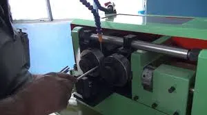
Automatic nut and bolt threading rod thread rolling machine
Chapter 4: Factors to Consider in Thread Rolling
Like any other machining process, there are several factors to consider ensuring optimum operating conditions and product quality. Listed below are some of the most significant variables affecting thread rolling.

- Material Requirements: A known disadvantage of thread rolling is its incompatibility with hard materials. The materials to be rolled must have a hardness not greater than HRC 40. Materials that can be rolled are low-carbon steels, mild steels, stainless steels, copper alloys, and often, aluminum. Moreover, the material must have the right degree of ductility. The recommended range is 12 to 20% elongation factor.
-
Stock Diameter: The correct stock diameter is almost the same as the pitch diameter of the screw or bolts. Usually, the space or cavity between the threads and below the pitch line is the same as the volume of the thread above the pitch line. Some adjustments for tolerances may be needed to attain the desired crest formation, especially if secondary processes such as coating, or plating are needed to be done.

- Chamfer Angle: Chamfer is the tapered conical surface at the start of a thread. Before rolling, the edge at one end of the stock must be machined to have a chamfer. A correct chamfer angle must be set to properly shape the thread at the end. The recommended chamfer angle is 30° for most cases.
-
Feeding: There are three basic techniques for feeding the stock into the dies: radial infeed, tangential feed, and through feed. In radial infeed, the dies move radially towards the axis of the stock. For tangential feed, the pitch of the stock approaches the rollers from its side making square, tangential contact. Lastly, through feed involves a cylindrical die that mates against the stock causing it to move axially.

- Thread Rolling Speeds: Thread rolling speeds depend on the mechanical and power limitations of the machine, the thread diameter, and the material and hardness of the metal stock. Rolling speeds can range from 30 to 100 m/min. Low rolling speeds are required for hard materials while high speeds are for soft and ductile materials.
- Coolant and Lubricant: Coolants or cutting fluids are extensively used in thread cutting, but these are also necessary for thread rolling. Deforming the metal also generates heat which can compromise both the dies and stock. Moreover, coolants can act also as lubricants to reduce the friction between the dies and stock.
Chapter 5: Common Defects
Though the thread rolling process offers higher precision than others, upsets and irregularities in the operation will inevitably create defects. Most of the defects arise from the out-of-tolerance stock dimensions, worn-out or misaligned rollers, and improper stock feeding. Below are the most common defects seen in thread rolling.
-
Truncated Thread Crest: This defect is described by a non-fully formed crest or an excessively truncated crest. One reason could be an undersized stock where there is insufficient material to flow and create the crests. This is fixed by gradually increasing the size of the stock. If the pitch diameter is oversized, then the more probable root cause is a loose threading head which is solved by sizing-in. If not, then the defect is possibly caused by too much hardness of the material. Thus, it is then necessary to change into a softer material.

- Flaking: Flaking or slivers causes unusual roughness on the surface of the threads. This is usually caused by the incompatibility of the material for rolling. The root causes can be excessive lead and sulfur content, inconsistent grain structure, and sometimes cold working before rolling. If the material being used already has a good rollability, then other possible causes can be mismatched rollers or dies, rough roller surface, overfilling, or slow rolling speeds.
- Drunken Threads: This defect is seen as wavy or uneven thread crests. This is a result of mismatched dies, misaligned feeding of the stock, or poor die construction. The best solution is to check the condition of the rolls and their bushings.
-
Curved Pitch Line: This is viewed as the tapering of the threads towards the ends of the threaded segments of the bolt or screw. The curvature can be concave or convex. Its root causes are inconsistent stock diameter, misaligned stock relative to the roller, wearing of rollers, or too much deformation of the material causing it to flow towards the end of the stock.

- Out-of-tolerance Helix Angle: This can be a result of a variety of causes such as unsynchronized rollers, imperfect rollers, incorrect feeding of the stock, or screw jacking. This can be solved by correctly timing and aligning the rollers, proper stock feeding, and optimizing the rolling speed.
- Poor Finish: Poor finish is a result of factors such as worn-out dies, high material hardness, oversized stock diameter, or presence of contaminants in the coolant supply.
-
Cupped End: A cupped end appears as a concave-end caused by forcing the metal to flow over an insufficient chamfer. This is more evident on softer metals. The defect is solved by properly chamfering the stock, usually about 30°.

Chapter 6: Types of Thread Rolling Machines
Thread rolling is a straightforward process where a metal bar is initially cut to length and forged to make the bolt or screw head. Afterward, it is machined to attain the right stock diameter and chamfer on one end. It is then fed into the threading machine where it passes through dies which form the shape of the thread. After rolling, the stock is then sent to secondary processes such as plating, anodizing, and coating.
This process summary is true to any type of thread rolling. There are different types of thread rolling machines that vary according to the type of die used. Thread rolling machines can be a flat-die, planetary, or cylindrical-die type.
-
Flat-die Type: This type of thread rolling machine consists of two rectangular dies where one is stationary while the other is reciprocating. The reciprocating die moves parallel to the stationary die. The surface of the dies contains ridges representing the profile of the thread to be produced. These ridges are inclined at an angle equal to the helix angle of the thread. The distance between the crests of the dies is equal to the minor diameter of the thread.

The threads are formed typically in one passage only. The length of the die allows the stock to be rolled around six to eight times. The stock is inserted on one end, either manually or automatically. The dies roll the stock tangentially which carries it up to the opposite end by friction.
-
Segment or Planetary Type: A planetary type operates by rolling the stock through one stationary and one moving surface. However, this machine uses rotating motion instead of translation. This type involves stationary curved dies and a central rotating die. One or more stationary dies can be matched with a single rotating die. A stationary die rolls one stock at a time.

Similar to the flat-die type, the planetary machine has a finite rolling surface that forms the thread through one passage. The stock is inserted on one end of the curved die. The rotating die then rotates a full arc of the curved die revolving the stock until ejected on the opposite end.
-
Cylindrical-die Type: Cylindrical dies or rollers are regarded as dies with infinite work surfaces. These machines usually operate through the combination of radial and through feeding. Unlike the flat-die and planetary types, the cylindrical-die type deforms the metal through multiple passes as it rolls. Cylindrical-die type machines can be further divided into two major categories: two-die and three-die machines.

- Two-die: This type of threading machine has two parallel rollers wherein one or both can move radially to accept and penetrate the stock. The stock is positioned with a slight offset from the plane of the centerline of the dies to prevent it from rising out. A smooth roller support or rest bar is located in the middle to hold the stock as it is being threaded.
- Three-die: This machine has three rollers positioned 120° from each other. Typically, all rollers can move radially wherein the position of the stock is maintained at the center during penetration. Compared with two-die machines, three-die types have better force balance but are more difficult and complex to adjust.
Conclusion
- Thread rolling is a type of threading process which involves deforming a metal stock by rolling it through dies to form external threads along its surface. Internal threads can be formed using the same principle, specifically termed thread forming.
- The processes of generating threads are generally classified into three methods: subtractive, deformative, and additive. These differ on how the thread is shaped or formed.
- The main advantage of thread rolling is the stronger surface and dimensional accuracy of the product. However, the process is limited to soft metals and requires more expensive tooling.
- There are different types of thread rolling machines that vary according to the type of die used. Thread rolling machines can be a flat-die, planetary, or cylindrical-die type.